Luckfox Pico Pro Max笔记
LuckFox pico Pro/Max
一、命令
1.1、修改系统时间
1 | |
1.2、后台执行任务
当在窗口运行一个死循环程序时,终端会一直等待进程完成,无法输入其他命令。如果你想在后台运行任务而不锁定终端,可以在命令末尾添加
&符号。如: python main.py&。
二、添加库
2.1、python添加MQTT库
2.1.1 添加步骤
1 | |
2.1.2测试
测试使用OneNet的MQTT服务器,需要从平台上获取到:设备ID、产品ID、鉴权信息。将下面的程序,修改星号处信息,直接复制到开发板上运行即可。
1 | |
2.2、添加ffmpeg支持
1 | |
三、添加设备
3.1 添加屏幕(2.8 inch st7789v 320*240)
3.1.1 修改设备树
在设备树文件的根下,添加引脚
2
3
4
5
6
7
8
9
10
11
12
13
14
15
16
17
18
19
20
21
22
23
24
25// add by Wei Ruitong ,23/12/17
/*LCD_CS -- USE MISO*/
gpio1pc3:gpio1pc3 {
compatible = "regulator-fixed";
pinctrl-names = "default";
pinctrl-0 = <&gpio1_pc3>;
regulator-name = "gpio1_pc3";
regulator-always-on;
};
/*LCD_DC*/
gpio1pd0:gpio1pd0 {
compatible = "regulator-fixed";
pinctrl-names = "default";
pinctrl-0 = <&gpio1_pd0>;
regulator-name = "gpio1_pd0";
regulator-always-on;
};
/*LCD_RES*/
gpio1pd1:gpio1pd1 {
compatible = "regulator-fixed";
pinctrl-names = "default";
pinctrl-0 = <&gpio1_pd1>;
regulator-name = "gpio1_pd1";
regulator-always-on;
};pinctrl 配置引脚的电气属性
2
3
4
5
6
7
8
9
10
11
12
13
14
15
16
17
18
19
20
21
22
23
24
25
26
27
28
29
30
31
32&pinctrl {
/*LCD_CS -- USE MISO*/
gpio1-pc3 {
gpio1_pc3:gpio1-pc3 {
rockchip,pins = <1 RK_PC3 RK_FUNC_GPIO &pcfg_pull_none>;
};
};
/*LCD_DC*/
gpio1-pd0 {
gpio1_pd0:gpio1-pd0 {
rockchip,pins = <1 RK_PD0 RK_FUNC_GPIO &pcfg_pull_none>;
};
};
/*LCD_RES*/
gpio1-pd1 {
gpio1_pd1:gpio1-pd1 {
rockchip,pins = <1 RK_PD1 RK_FUNC_GPIO &pcfg_pull_none>;
};
};
spi0 {
/omit-if-no-ref/
spi0m0_pins: spi0m0-pins {
rockchip,pins =
/* spi0_clk_m0 */
<1 RK_PC1 4 &pcfg_pull_none>,
/* spie_miso_m0 */
/* <1 RK_PC3 6 &pcfg_pull_none>, */
/* spi_mosi_m0 */
<1 RK_PC2 6 &pcfg_pull_none>;
};
};
};在spi节点下添加st7789设备
2
3
4
5
6
7
8
9
10
11
12
13
14
15
16
17
18
19
20
21
22
23
24
25
26
27
28
29
30&spi0 {
status = "okay";
pinctrl-names = "default";
pinctrl-0 = <&spi0m0_pins>;
// cs-gpios = <&gpio1 RK_PC0 1>;
// cs-gpios = <&gpio1 26 1>;
#address-cells = <1>;
#size-cells = <0>;
/*
spidev@0 {
compatible = "rockchip,spidev";
spi-max-frequency = <1000000000>;
reg = <0>;
};
*/
st7789v: st7789v@0{
status = "okay";
compatible = "sitronix,st7789v";
spi-max-frequency = <48000000>;
reg = <0>;
rotate = <90>;
fps = <60>;
rgb;
buswidth = <8>;
dc-gpios = <&gpio1 RK_PD0 GPIO_ACTIVE_HIGH>;
reset-gpios = <&gpio1 RK_PD1 GPIO_ACTIVE_LOW>;
cs-gpios = <&gpio1 RK_PC3 GPIO_ACTIVE_LOW>;
};
};背光调节,在根路径下添加如下代码,使用的是pwm5_m1,即引脚GPIO2_B0_d
2
3
4
5
6
7
8
9
10lcd_backlight:backlight {
compatible = "pwm-backlight";
pinctrl-names = "default";
pinctrl-0 = <&pwm5m1_pins>;
status = "okay";
pwms = <&pwm5 0 500000 0>;
pwm-names = "backlight";
brightness-levels = <0 4 8 16 32 64 128 255>;
default-brightness-level = <7>;
};
3.1.2 内核添加设备
在kernal目录下
2cp ./arch/arm/configs/luckfox_rv1106_linux_defconfig .config
make ARCH=arm menuconfig、执行
make menuconfig命令使能
Device Drivers > Staging Drivers > Support for small TFT LCD display modules > FB Driver for the ST7789V LCD Controller使能SPI中的选项
2
3
4
5CONFIG_SPI_MASTER=y
CONFIG_SPI_DESIGNWARE=y
CONFIG_SPI_DW_MMIO=y使能FB中的其他选项
2
3CONFIG_FB=y
CONFIG_FB_TFT=y保存
2make ARCH=arm savedefconfig
cp defconfig ./arch/arm/configs/luckfox_rv1106_linux_defconfig回到/home路径下,不要clean项目,否侧配置会丢失,直接编译
2
3
4
5// 选择开发板MAX,4
./build.sh lunch
// 编译项目
./build.sh
3.1.3 测试
1 | |

3.2 添加触摸屏(GT911)
3.2.1 修改设备树
在根节点中定义中断和复位GPIO
2
3
4
5
6
7
8
9
10
11
12
13
14
15
16
17/*TOUCH_RST*/
gpio1pc0:gpio1pc0 {
compatible = "regulator-fixed";
pinctrl-names = "default";
pinctrl-0 = <&gpio1_pc0>;
regulator-name = "gpio1_pc0";
regulator-always-on;
};
/*TOUCH_INT*/
gpio2pb1:gpio2pb1 {
compatible = "regulator-fixed";
pinctrl-names = "default";
pinctrl-0 = <&gpio2_pb1>;
regulator-name = "gpio2_pb1";
regulator-always-on;
};在pinctrl中配置GPIO属性
2
3
4
5
6
7
8
9
10
11
12/* TOUCH_INT */
gpio1-pc0 {
gpio1_pc0:gpio1-pc0 {
rockchip,pins = <1 RK_PC0 RK_FUNC_GPIO &pcfg_pull_none>;
};
};
/* TOUCH_RST */
gpio2-pb1 {
gpio2_pb1:gpio2-pb1 {
rockchip,pins = <2 RK_PB1 RK_FUNC_GPIO &pcfg_pull_none>;
};
};在pinctrl中配置I2C3引脚
2
3
4
5
6
7
8
9
10i2c3 {
/omit-if-no-ref/
i2c3m1_xfer: i2c3m1-xfer {
rockchip,pins =
/* i2c3_scl_m1 */
<1 RK_PD3 3 &pcfg_pull_up>,
/* i2c3_sda_m1 */
<1 RK_PD2 3 &pcfg_pull_up>;
};
};在I2C3中添加gt911设备,注意设备地址0x14 或 0x5d中的一个
2
3
4
5
6
7
8
9
10
11
12
13
14
15
16
17
18
19
20
21&i2c3 {
status = "okay";
pinctrl-names = "default";
pinctrl-0 = <&i2c3m1_xfer>;
clock-frequency = <400000>;
gt911: gt911@14 {
compatible = "goodix,gt911";
reg = <0x14>;
interrupt-parent = <&gpio1>;
interrupts = <RK_PC0 IRQ_TYPE_EDGE_FALLING>;
pinctrl-names = "default";
//pinctrl-0 = <&gpio2_pb1 &gpio1_pc0>;
reset-gpios = <&gpio2 RK_PB1 GPIO_ACTIVE_LOW>;
irq-gpios = <&gpio1 RK_PC0 GPIO_ACTIVE_LOW>;
touchscreen-size-y = <240>;
touchscreen-size-x = <320>;
/* touchscreen-inverted-x; */
/* touchscreen-inverted-y; */
/* touchscreen-swapped-x-y;*/
};
3.2.2 内核添加触摸设备
- make menuconfig
- 使能 Device Drivers > Input device support >Touchreens > Goodix I2C touchscreen
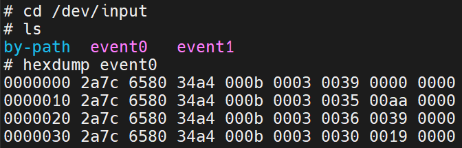
3.2.3 测试
系统信息
进入
/dev/input目录能够看到比原来多了一个event,使用hexdump命令查看,触摸屏幕,会打印如下信息

3.2.4 问题
玩lvgl时发现触摸点和响应点不是一个点。
答:屏幕驱动方向的问题,两种方法更改
2
3
4
5
6
7
8
9// 在设备树gt911节点下进行更改
/* touchscreen-inverted-x; */
/* touchscreen-inverted-y; */
/* touchscreen-swapped-x-y;*/
// 在lv_drivers的配置文件lv_drv_config.h中更改
# define EVDEV_SWAP_AXES 1 /*Swap the x and y axes of the touchscreen*/
//可结合两种方式自行调整如果上述各种组合都无法解决问题(比如上下滑动正常,单左右滑动反了,可参考如下解决办法),又不想修改linux自带的goodix驱动,可以修改
lv_drivers/indev/evdev.c文件,注意这里已经使能EVDEV_SWAP_AXES宏了,如果未使能,修改else中的内容即可。
2
3
4
5
6
7
8
9
10
11
12
13
14
15
16
17
18
19
20
21
22
23
24
25
26
27
28// 比如我的上下滑动正常,但是左右滑动刚好相反
// 找到文件中的evdev_read()函数,局部代码如下
// 可以使用printf()函数,输出当前坐标,比如左上角就应该是(0,0)坐标,右下角应该是(320,240)
// 如果和你预想的不一样,需要根据情况进行调整
if(in.code == ABS_X)
#if EVDEV_SWAP_AXES
evdev_root_y = in.value;
#else
evdev_root_x = in.value;
#endif
else if(in.code == ABS_Y)
#if EVDEV_SWAP_AXES
evdev_root_x = 320 - in.value; // 左右刚好相反,用横最大像素减去当前像素,才是真实的触点
#else
evdev_root_y = in.value;
#endif
else if(in.code == ABS_MT_POSITION_X)
#if EVDEV_SWAP_AXES
evdev_root_y = in.value;
#else
evdev_root_x =in.value;
#endif
else if(in.code == ABS_MT_POSITION_Y)
#if EVDEV_SWAP_AXES
evdev_root_x = 320 - in.value; // 同理
#else
evdev_root_y = in.value;
#endif
3.3 温湿度DHT11
修改设备树,并注释掉UART4,应为公用了同一个引脚,具体使用方法可看kernel目录下的dht11.txt文档
kernel/Documentation/devicetree/bindings/iio/humidity/dht11.txt1
2
3
4
5
6
7
8
9
10
11
12
13
14
15
16
17/{
humidity_sensor {
compatible = "dht11";
pinctrl-names = "default";
status = "okay";
pinctrl-0 = <&gpio1_pc4>;
gpios = <&gpio1 RK_PC4 GPIO_ACTIVE_HIGH>;
};
};
&pinctrl {
gpio1-pc4 {
gpio1_pc4:gpio1-pc4 {
rockchip,pins = <1 RK_PC4 RK_FUNC_GPIO &pcfg_pull_none>;
};
};
};kernel中打开dht11驱动
1
2
3make menuconfig
# 使能
Device Drivers > Industrial I/O support > Humidity sensors驱动报错
[ 24.069548] dht11 humidity_sensor: Don't know how to decode data: 95 0 25 2,正常情况下温湿度均不会返回小数部分。但是返回了,就不知道如何解析数据了。可以修改dht11.c文件的大概152行的部分代码。1
2
3
4
5
6
7
8
9
10
11
12
13
14
15if (hum_int < 4) { /* DHT22: 100000 = (3*256+232)*100 */
dht11->temperature = (((temp_int & 0x7f) << 8) + temp_dec) *
((temp_int & 0x80) ? -100 : 100);
dht11->humidity = ((hum_int << 8) + hum_dec) * 100;
// } else if (temp_dec == 0 && hum_dec == 0) { /* DHT11 */
}else{
dht11->temperature = temp_int * 1000;
dht11->humidity = hum_int * 1000;
}
// } else {
// dev_err(dht11->dev,
// "Don't know how to decode data: %d %d %d %d\n",
// hum_int, hum_dec, temp_int, temp_dec);
// return -EIO;
// }应用程序
1
2
3
4
5
6
7
8
9
10
11
12
13
14
15
16
17
18
19
20
21
22
23
24
25
26
27
28
29
30
31
32
33
34
35
36
37
38
39
40
41
42
43
44
45
46
47
48
49void getHumidityandTemperature(lv_timer_t *timer)
{
int temperature_file, humidity_file;
temperature_file = open("/sys/bus/iio/devices/iio:device1/in_temp_input", O_RDONLY);
humidity_file = open("/sys/bus/iio/devices/iio:device1/in_humidityrelative_input", O_RDONLY);
if (temperature_file == -1 || humidity_file == -1)
{
perror("Open dhtll files error!\n");
exit(EXIT_FAILURE);
}
// 读取温度值
char temp_buf[5];
ssize_t bytesRead = read(temperature_file, temp_buf, sizeof(temp_buf) - 1);
if (bytesRead == -1)
{
// perror("Error reading temperature file!\n");
close(temperature_file);
// exit(EXIT_FAILURE);
return;
}
temp_buf[bytesRead] = '\0';
close(temperature_file);
int temperature = atoi(temp_buf)/100;
memset(temp_buf, 0, sizeof(temp_buf));
sprintf(temp_buf, "%d°C", temperature);
// 读取湿度值
char humid_buf[5];
ssize_t bytesRead2 = read(humidity_file, humid_buf, sizeof(humid_buf) - 1);
if (bytesRead2 == -1)
{
// perror("Error reading humidity file!\n");
close(humidity_file);
// exit(EXIT_FAILURE);
return;
}
humid_buf[bytesRead2] = '\0';
close(humidity_file);
int humidity = atoi(humid_buf)/100;
memset(humid_buf, 0, sizeof(humid_buf));
sprintf(humid_buf, "%d%cRH", humidity,'%');
// 修改界面
lv_label_set_text(ui_templable, temp_buf);
lv_bar_set_value(ui_tempbar, temperature, LV_ANIM_ON);
lv_label_set_text(ui_humilable, humid_buf);
lv_bar_set_value(ui_humibar, humidity, LV_ANIM_ON);
}
四、摄像头(SC3336)
五、LVGL应用
4.1 移植LVGL
github下载仓库代码lv_port_linux_frame_buffer 、lvgl-release-v8.3,将lv_port_linux_frame_buffer文件夹中的lvgl替换成新下载的lvgl,
将lv_port_linux_frame_buffer文件夹中的lv_conf.h配置文件替换成lvgl文件夹中的lv_conf_templent文件,并重新命名为lv_conf.h。
拷贝一份lv_port_linux_frame_buffer,并重命名为myui(名字可以随便起).
1
2
3
4git clone -b release/v8.3 https://github.com/lvgl/lvgl.git
git clone https://github.com/lvgl/lv_port_linux_frame_buffer.git
cd lv_port_linux_frame_buffer/
git submodule update --init --recursive修改lv_drivers配置文件lv_drv_conf.h
默认已使能linux屏幕frambuffer
1
2
3
4
5
6
7#ifndef USE_FBDEV
# define USE_FBDEV 1
#endif
#if USE_FBDEV
# define FBDEV_PATH "/dev/fb0"
#endif默认已经使能linux触摸屏幕,只需要修改触摸事件的路径和屏幕尺寸,我的是
/dev/input/event0,尺寸是320*2401
2
3
4
5
6
7
8
9
10
11
12
13
14
15
16
17
18
19
20
21#ifndef USE_EVDEV
# define USE_EVDEV 1
#endif
#ifndef USE_BSD_EVDEV
# define USE_BSD_EVDEV 0
#endif
#if USE_EVDEV || USE_BSD_EVDEV
# define EVDEV_NAME "/dev/input/event0" /*You can use the "evtest" Linux tool to get the list of devices and test them*/
# define EVDEV_SWAP_AXES 0 /*Swap the x and y axes of the touchscreen*/
# define EVDEV_CALIBRATE 0 /*Scale and offset the touchscreen coordinates by using maximum and minimum values for each axis*/
# if EVDEV_CALIBRATE
# define EVDEV_HOR_MIN 0 /*to invert axis swap EVDEV_XXX_MIN by EVDEV_XXX_MAX*/
# define EVDEV_HOR_MAX 320 /*"evtest" Linux tool can help to get the correct calibraion values>*/
# define EVDEV_VER_MIN 0
# define EVDEV_VER_MAX 240
# endif /*EVDEV_CALIBRATE*/
#endif /*USE_EVDEV*/
修改lvgl配置文件lv_conf.h
- 使能配置文件
1
2
3
4
5// 将if 0 改为 if 1
#if 1 /*Set it to "1" to enable content*/
#ifndef LV_CONF_H
#define LV_CONF_H- 修改屏幕色深
1
2/*Color depth: 1 (1 byte per pixel), 8 (RGB332), 16 (RGB565), 32 (ARGB8888)*/
#define LV_COLOR_DEPTH 16 // 这里我的是16- 使能malloc函数
1
2// 将该宏设为1
#define LV_MEM_CUSTOM 1- 使能时钟,修改系统时钟头文件,修改时间函数
1
2
3
4
5
6
7
8#define LV_TICK_CUSTOM 1
#if LV_TICK_CUSTOM
#define LV_TICK_CUSTOM_INCLUDE "stdint.h" /*Header for the system time function*/
#define LV_TICK_CUSTOM_SYS_TIME_EXPR (custom_tick_get()) /*Expression evaluating to current system time in ms*/
/*If using lvgl as ESP32 component*/
// #define LV_TICK_CUSTOM_INCLUDE "esp_timer.h"
// #define LV_TICK_CUSTOM_SYS_TIME_EXPR ((esp_timer_get_time() / 1000LL))
#endif /*LV_TICK_CUSTOM*/- 使能一个测试demo,只在中文注释的行进行修改
1
2
3
4
5
6
7
8
9
10
11
12
13
14#define LV_USE_DEMO_WIDGETS 1 //这里设为1
#if LV_USE_DEMO_WIDGETS
#define LV_DEMO_WIDGETS_SLIDESHOW 0
#endif
/*Demonstrate the usage of encoder and keyboard*/
#define LV_USE_DEMO_KEYPAD_AND_ENCODER 0
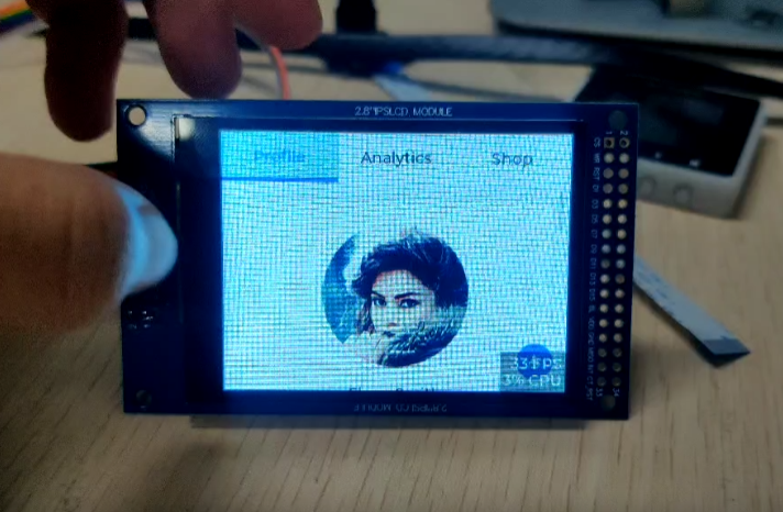
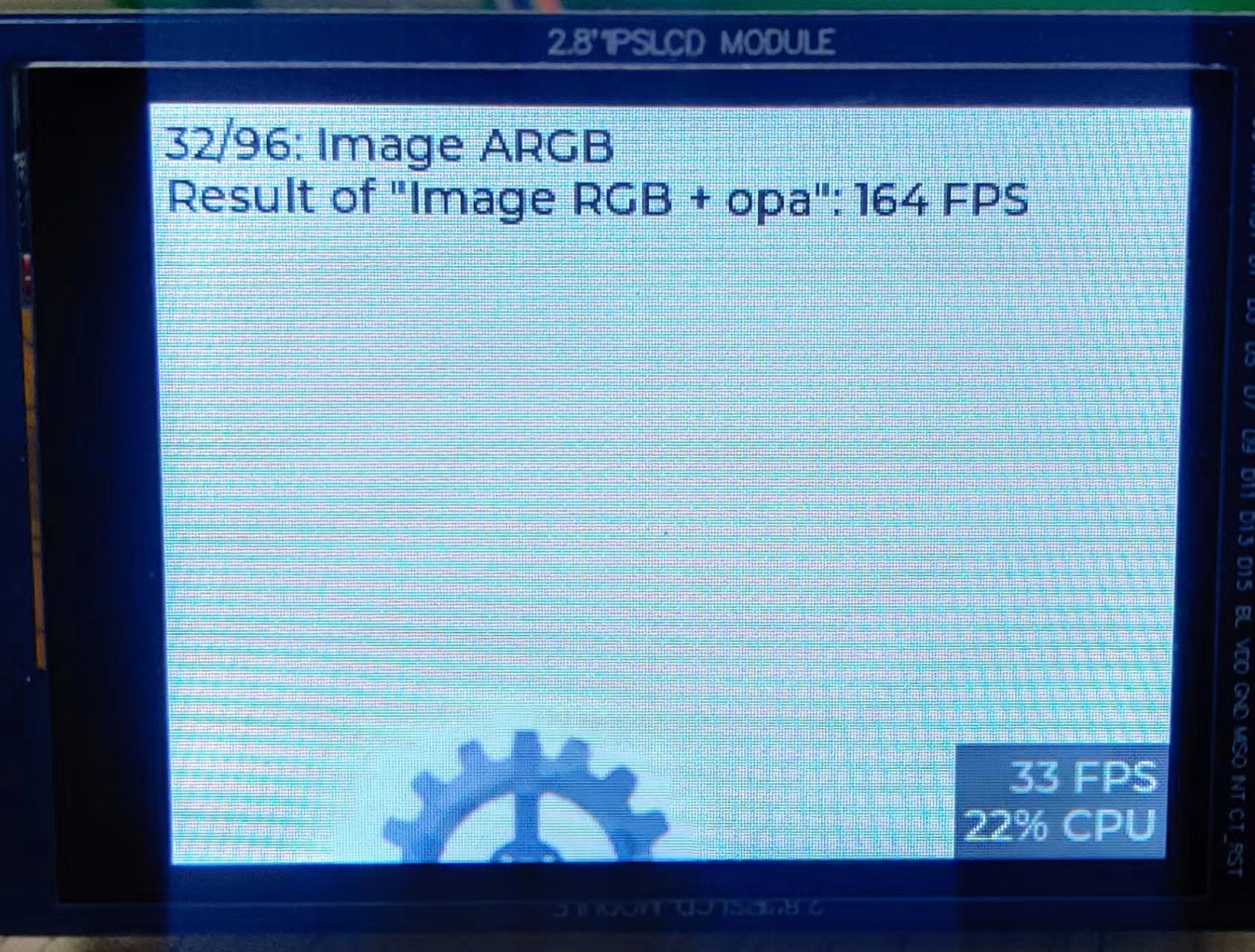
/*Benchmark your system*/
#define LV_USE_DEMO_BENCHMARK 1 //使能该demo,其他的也可以
#if LV_USE_DEMO_BENCHMARK
/*Use RGB565A8 images with 16 bit color depth instead of ARGB8565*/
#define LV_DEMO_BENCHMARK_RGB565A8 0
#endif修改 main.c 文件
修改屏幕尺寸,注释鼠标设备
1
2
3
4
5
6
7
8
9
10
11
12
13
14
15
16
17
18// 这里将buf设置为屏幕的尺寸那么大,更大也可以
#define DISP_BUF_SIZE (320 * 240)
// 注册屏幕设备的地方,修改屏幕尺寸
static lv_disp_drv_t disp_drv;
lv_disp_drv_init(&disp_drv);
disp_drv.draw_buf = &disp_buf;
disp_drv.flush_cb = fbdev_flush;
disp_drv.hor_res = 320;
disp_drv.ver_res = 240;
lv_disp_drv_register(&disp_drv);
// 注释掉鼠标设备的支持
/*Set a cursor for the mouse*/
// LV_IMG_DECLARE(mouse_cursor_icon)
// lv_obj_t * cursor_obj = lv_img_create(lv_scr_act()); /*Create an image object for the cursor */
// lv_img_set_src(cursor_obj, &mouse_cursor_icon); /*Set the image source*/
// lv_indev_set_cursor(mouse_indev, cursor_obj); /*Connect the image object to the driver*/修改ui代码,默认使用的是lv_demo_widgets()的示例,可将其修改成其他的示例,或者自己用SquareLine Studio 编写的ui界面
1
2
3// 修改ui,可以调用自己用SquareLine Studio生成的ui界面程序
// lv_demo_widgets();
lv_demo_benchmark();
编译与运行方法一:Makefile方式
1
2
3
4
5
6
7
8
9
10
11
12
13
14
15
16
17
18
19
20
21
22
23
24
25
26
27
28
29
30
31
32
33
34
35
36修改Makefile
***********************************************************************************************************************
// 添加交叉编译工具链
CC = <SDK目录>/tools/linux/toolchain/arm-rockchip830-linux-uclibcgnueabihf/bin/arm-rockchip830-linux-uclibcgnueabihf-gcc
# 注释掉下面这行
# CSRCS +=$(LVGL_DIR)/mouse_cursor_icon.c
# 可以修改生成的执行文件的名字
BIN = demo
编译与运行
***********************************************************************************************************************
// 使用最上层的MakeFile编译项目
// 编译
make
// 如果感觉编译比较慢,可以查看自己的电脑核心数,如下16是核心数,并行会快很多
make -j16
// 清除
make clean
// 查看编译好的文件,file + 文件名
file demo
// 生成了ARM架构,32位,小端,可执行文件
demo: ELF 32-bit LSB executable, ARM, EABI5 version 1 (SYSV), dynamically linked, interpreter /lib/ld-uClibc.so.0,
with debug_info, not stripped
// 将可执行文件拷贝到开发板上
scp demo root@ip地址:/root
//执行
./demo //将占用命令窗口
./demo& //后台执行编译与运行方法二:cmake方式
1
2
3
4
5
6
7
8
9
10
11
12
13
14
15
16
17
18修改CMakeLists.txt文件
***********************************************************************************************************************
set(CMAKE_SYSTEM_NAME Linux) // 设置目标系统
set(CMAKE_SYSTEM_PROCESSOR arm) // 设置目标架构
// 设置C/C++交叉编译工具链
set(TOOLCHAINPATH /home/wrt/LuckFox/Max/luckfox-pico/tools/linux/toolchain/arm-rockchip830-linux-uclibcgnueabihf)
set(CMAKE_C_COMPILER ${TOOLCHAINPATH}/bin/arm-rockchip830-linux-uclibcgnueabihf-gcc)
set(CMAKE_CXX_COMPILER ${TOOLCHAINPATH}/bin/arm-rockchip830-linux-uclibcgnueabihf-g++)
编译与运行
***********************************************************************************************************************
mkdir build
cd build
cmake ..
make 或 make -j16
#此时会在build文件夹生成目标平台的可执行文件
#将文件拷贝到开发板上执行即可运行结果
4.2 移植文件系统
很简单,打开lvgl的配置文件,打开下面的宏,即可
2
3
4
5
6
7
8/*API for fopen, fread, etc*/
#define LV_USE_FS_STDIO 1 // 使用c标准api接口,fopen
#if LV_USE_FS_STDIO
#define LV_FS_STDIO_LETTER 'S' /*Set an upper cased letter on which the drive will accessible (e.g. 'A')*/
#define LV_FS_STDIO_PATH "" /*Set the working directory. File/directory paths will be appended to it.*/
// 设置读取文件的缓存cache大小,根据硬件条件设置大小,设置为1024 Bytes
#define LV_FS_STDIO_CACHE_SIZE 1024 /*>0 to cache this number of bytes in lv_fs_read()*/
#endif用下面函数测试:
2
3
4
5
6
7
8
9
10
11
12
13
14
15
16
17
18
19
20
21
22
23
24
25
26
27
28
29
30
31
32
33
34
35
36
37
38
39
40void FileTest(void)
{
lv_fs_dir_t dir;
lv_fs_res_t res;
res = lv_fs_dir_open(&dir, "S:/");
char fn[256];
while(1) {
res = lv_fs_dir_read(&dir, fn);
if(strlen(fn) == 0) {
break;
}
printf("%s\n", fn);
}
lv_fs_dir_close(&dir);
}
// 执行结果,能够看到打印改文件夹中的内容
# ./luckfoxmax
/bin
/dev
/etc
/lib
/mnt
/oem
/opt
/run
/tmp
/sys
/var
/usr
data
/proc
/sbin
/root
linuxrc
/userdata
/rockchip_test
lib32
lib64
/media
4.3 cmake的使用
其实,lvgl的工程是一个cmake工程,在项目根目录建立build文件夹,进入build文件夹,执行==
cmake ..==指令,会在该目录下面生成Makefile文件,然后在执行make指令,一样会编译出可执行文件。那么对于后期使用cmake需要修改哪些东西呢?
修改根路径下的==CMakeLists.txt==文件,添加交叉编译环境,在project上方,不然可能提示找不到交叉编译工具链
2
3
4set(TOOLCHAINPATH /home/wrt/LuckFox/Max/luckfox-pico/tools/linux/toolchain/arm-rockchip830-linux-uclibcgnueabihf)
set(CMAKE_C_COMPILER ${TOOLCHAINPATH}/bin/arm-rockchip830-linux-uclibcgnueabihf-gcc)
set(CMAKE_CXX_COMPILER ${TOOLCHAINPATH}/bin/arm-rockchip830-linux-uclibcgnueabihf-g++)
project(luckfoxmax)设置目标平台的操作系统、处理器架构
2
3cmake_minimum_required(VERSION 3.1)
set(CMAKE_SYSTEM_NAME Linux)
set(CMAKE_SYSTEM_PROCESSOR arm)如果文件A中引用了B头文件,则需要在A的CMakeLists.txt下添加头文件路径
2
3
4
5// 如果路径引用到头文件中的最后一个目录,这可以这样引用头文件
# include<B.h>
// 如果路径没有包含到头文件的最后一层文件夹,则应用头文件需要带上文件夹:如
# include<curl/curl.h>
include_directories(B_HEAD_PATH)链接库,添加头文件
2
3
4
5
6
7
8
9
10
11
12
13
14# 比如要使用curl库获取天气信息,并使用cjson库解析json数据,则需要引用如下库
target_link_libraries(${PROJECT_NAME} PRIVATE ${LINK_PATH}/libssl.so.1.1)
target_link_libraries(${PROJECT_NAME} PRIVATE ${LINK_PATH}/libcrypto.so.1.1)
target_link_libraries(${PROJECT_NAME} PRIVATE ${LINK_PATH}/libcurl.so.4.8.0)
target_link_libraries(${PROJECT_NAME} PRIVATE ${LINK_PATH}/libz.so.1.2.13)
target_link_libraries(${PROJECT_NAME} PRIVATE ${LINK_PATH}/libcjson.so.1.7.15)
# 库链接了,使用的时候需要头文件,要包含头文件的路径
include_directories(${HEADS_PATH}/libcurl-8.4.0/include/)
include_directories(${HEADS_PATH}/cjson-1.7.15)
include_directories(${HEADS_PATH}/libopenssl-1.1.1v/include/openssl)
include_directories(${HEADS_PATH}/libzlib-1.2.13)
# 这些库在本机的位置如下
set(HEADS_PATH /home/wrt/LuckFox/Max/luckfox-pico/sysdrv/source/buildroot/buildroot-2023.02.6/output/build)
set(LINK_PATH /home/wrt/LuckFox/Max/luckfox-pico/output/out/rootfs_uclibc_rv1106/usr/lib)上层CMakeLists.txt添加下层子目录
2
3add_subdirectory(lvgl)
add_subdirectory(lv_drivers)
add_subdirectory(components)依赖另一个文件的头文件
target_include_directories(lvgl PUBLIC ${CMAKE_CURRENT_SOURCE_DIR}/../../lvgl/)
4.4 Lottie动画移植
git clone https://github.com/Samsung/rlottie.git编译rlottie源代码
2
3
4# 首先修改项目的编译工具链,这里直接在CMakeLists.txt中修改了,也可以用其他方式
set(TOOLCHAINPATH /home/wrt/LuckFox/Max/luckfox-pico/tools/linux/toolchain/arm-rockchip830-linux-uclibcgnueabihf)
set(CMAKE_C_COMPILER ${TOOLCHAINPATH}/bin/arm-rockchip830-linux-uclibcgnueabihf-gcc)
set(CMAKE_CXX_COMPILER ${TOOLCHAINPATH}/bin/arm-rockchip830-linux-uclibcgnueabihf-g++)编译,报错
2
3
4
5
6
7
8
9
10
11
12
13
14
15
16
17
18
19
20
21
22
23
24
25
26
27
28
29
30
31
32
33
34
35
36
37
38
39
40
41
42
43
44
45
46
47
48
49
50// 编译
cd rlottie
mkdir build
cmake ..
make -j16
//大概是这样的错误
Undefined symbol _pixman_composite_over_n_8888_asm_neon
//解决办法,修改文件rlottie/src/vector/vdrawhelper_neon.cpp,整体替换为如下内容
//解决办法,在仓库issue中,也可以以打补丁的方式修改,内容很少,修改也很快
#if defined(__ARM_NEON__)
#include "vdrawhelper.h"
#include <string.h>
// extern "C" void pixman_composite_src_n_8888_asm_neon(int32_t w, int32_t h,
// uint32_t *dst,
// int32_t dst_stride,
// uint32_t src);
// extern "C" void pixman_composite_over_n_8888_asm_neon(int32_t w, int32_t h,
// uint32_t *dst,
// int32_t dst_stride,
// uint32_t src);
void memfill32(uint32_t *dest, uint32_t value, int length)
{
// pixman_composite_src_n_8888_asm_neon(length, 1, dest, length, value);
memset(dest, value, length);
}
static void color_SourceOver(uint32_t *dest, int length,
uint32_t color,
uint32_t alpha)
{
// if (const_alpha != 255) color = BYTE_MUL(color, const_alpha);
int ialpha, i;
// pixman_composite_over_n_8888_asm_neon(length, 1, dest, length, color);
if (alpha != 255) color = BYTE_MUL(color, alpha);
ialpha = 255 - vAlpha(color);
for (i = 0; i < length; ++i) dest[i] = color + BYTE_MUL(dest[i], ialpha);
}
void RenderFuncTable::neon()
{
updateColor(BlendMode::Src , color_SourceOver);
}
#endif编译通过,将动态链接库复制到开发板上的==/usr/lib==文件夹中,链接库如下
2
3
4# build目录下,建议都复制过去,虽然有两个是连接文件
librlottie.so
librlottie.so.0
librlottie.s0.0.2项目中连接动态库,包含头文件位置
2
3
4# 添加rlottie头文件
include_directories(/home/wrt/LuckFox/rlottie/inc)
# 链接librlottie库
target_link_libraries(${PROJECT_NAME} PRIVATE /home/wrt/LuckFox/rlottie/build/librlottie.so.0.2)使用测试
2
3
4
5
6
7# 以文件方式载入,注意这里不需要带文件系统标识符,因为使用的是rlottie的文件系统
lv_obj_t *lottie2 = lv_rlottie_create_from_file(ui_Panel3, 150, 110, "/mnt/sdcard/lottie_json/astronut.json");
lv_obj_center(lottie2);
# 从内存中直接载入
extern const uint8_t lottie_data[];
lv_obj_t* lottie = lv_rlottie_create_from_raw(parent, width, height, (const char *)lottie_data);
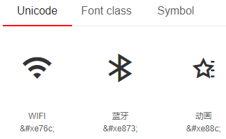
4.5 使用阿里巴巴矢量库字体
- 首先,去阿里巴巴矢量图标库,获取自己想要的资源。加入购物车后,选择下载资源。打开下载下来的html文件,例如:
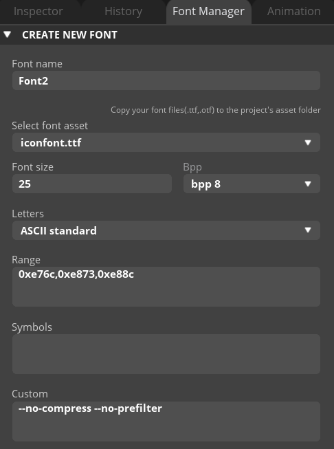
在SquareLine Studio 软件中添加字体
使用字体,千千秀字,复制下图中的对应字符到lable中,即可正常显示文字。